This hands-on tutorial explains how to setup a Modbus RTU server on an STM32 microcontroller system. We’ll use a Nucleo-F401RE board in combination with the STM32CubeIDE development environment. However, you can use any other STM32 microcontroller board.

The Modbus protocol is historically popular for interconnecting electronic devices in the fields of factory and building automation. Note though that its application goes way beyond that. Essentially, you can rely on Modbus anytime you require remote access to the inputs and outputs of a microcontroller. To name a few examples:
- I/O expander for a PC or embedded Linux device.
- Inter-communication between multiple microcontrollers on the same PCB.
Don’t dismiss the Modbus protocol based on its age. Sure, its origins date back all the way to the late 70s. Yet, it is such an elegant protocol that hits the sweet spot between simplicity and versatility. Thanks to this, new microcontroller based designs will still integrate Modbus functionality for decades to come.
The RTU part implies the use of an RS232 or RS485 physical communication link. Alternatively, you can simply crosslink the UART Rx and Tx lines, if the Modbus client and server form one system, e.g. they reside on the same PCB.
What do you need
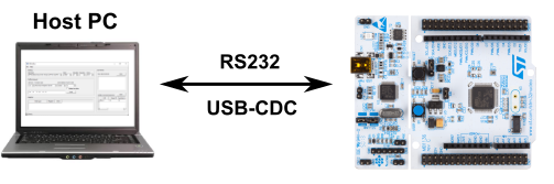
In this tutorial our PC acts as the Modbus RTU client (master) and the STM32 microcontroller as the Modbus RTU server (slave). RS232 communication works fine in such a single node network architecture:
To follow along with the hands-on part of this tutorial, you need the following:
- An STM32 board that you can program and connect to your PC’s serial port.
- The ST STM32CubeIDE installed on your PC.
- For Modbus RTU communication testing, the QModbus application installed on your PC.
I can highly recommend using one of the ST Nucleo boards for this tutorial. They come with an on-board ST-Link interface for programming and debugging. More importantly, the on-board ST-Link debugger additionally implements a USB-CDC device. Basically a build-in RS232-to-USB adapter, which connects one of the STM32’s USART peripherals to your PC’s virtual COM-port.
Essentially this means that we just need to connect the Nucleo board to our PC with a USB cable for:
- Powering the board.
- Programming and debugging our STM32 firmware.
- RS232 serial communication with the PC.
For this tutorial I selected the Nucleo-F401RE board. When it comes to the Modbus software stack, we’ll use Feaser’s own MicroTBX-Modbus.
Modbus RTU server specification
Let’s set some goals of what we intend to create. For the tutorial we’ll keep things as simple as possible. This gives you a good foundation, which you can easily extend to support more Modbus features. The specification for our Modbus RTU server:
- Node identifier: 10.
- Communication settings: 19200 bits/sec, 8 data-bits, 1 stop-bit and even parity.
- Number of communication channels: 1.
- Modbus data tables: Two 16-bit input registers starting at zero-based address
30000.
New STM32 project creation
As a first step, we create a new STM32 project in the STM32CubeIDE and use the integrated CubeMX tool to configure the microcontroller. Open the STM32CubeIDE application. It prompts you to select the workspace directory. You can accept the default proposed directory and it creates a new workspace for you, if one doesn’t yet exist in that directory.
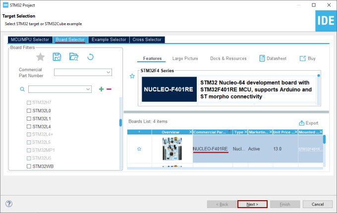
With the workspace opened, select File → New → STM32 Project from the menu. On the Target Selection dialog, select STM32 microcontroller or board that you intend to use:
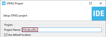
Enter the desired project name on the next screen of the new project wizard. I chose ModbusRtu:
Afterwards, complete the new project wizard by accepting all the proposed defaults. When asked to initialize all peripherals with the default mode, select Yes.
Clock configuration
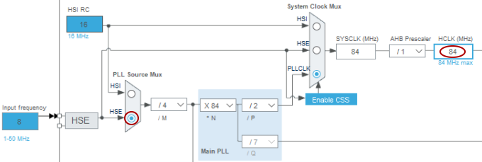
The project wizard selected the internal HSI RC oscillator as the system’s clock source and configured the PLL to increase the system clock (HCLK) to the maximum supported frequency, 84 MHz in the case of the STM32F401RE.
The internal factory calibrated HSI RC oscillator comes with a ±1% accuracy at room temperature. For RS232/RS485 baudrate generation, you need a clock accuracy in the ±2% range. Looking at the STM32F401RE’s datasheet, you’ll notice that the HSI RC accuracy changes with the microcontroller’s operating temperature. Over the -10 to 85 degrees Celsius range, the HSI RC unfortunately only guarantees a ±4% clock accuracy.
With the HSI RC oscillator, the RS232 communication will work for testing purposes with the system on your desk at room temperature. However, it is better to select a different clock source with better accuracy. For example an external crystal oscillator.
The Nucleo-F401RE board has two microcontrollers on it: One for the ST-Link debugger and the STM32F401RE for which we develop firmware. An external 8MHz crystal oscillator drives the ST-Link debugger. More interestingly, it outputs its clock signal on the MCO pin and offers it to the STM32F401RE. For USART baudrate accuracy purposes, it is better to use this externally offered clock signal (HSE) to source the PLL, instead of the HSI RC oscillator. For this reason, I switched the HSI clock to the HSE clock in the PLL Source Mux block:
USART configuration
For the Nucleo-F401RE board, the project wizard configured the PA2 and PA3 GPIO pins for USART2 transmit and receive functionality, respectively. These two USART pins are connected to the ST-Link debugger. In turn, the ST-Link debugger exposes them as a USB-CDC device to the PC. With other words, the USART2 communication peripheral on the STM32F401RE and the virtual COM port on the PC form an RS232 communication link.
We merely need to reconfigure the USART2 communication settings and enable its interrupt generation in the integrated CubeMX tool. According to our earlier selected Modbus RTU server goals, we need to configure the USART2 for these communication properties:
- Baudrate: 19200 bits/sec
- Data bits (excluding parity): 8 data-bits
- Stop bits: 1 stop-bit
- Parity: Even parity
Select the USART2 peripheral on tab Pinout & Configuration, update the USART2 parameter settings accordingly and enable the USART2 global interrupt:
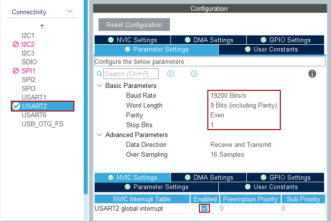
Note that you need to include the parity bit in the word length. Therefore set the Word Length to 9 (8 data-bits plus 1 parity-bit).
Timer configuration
The MicroTBX-Modbus stack needs a time reference. For example to monitor the Modbus RTU communication’s 1.5 and 3.5 character times. As opposed to most other Modbus software solutions, MicroTBX-Modbus does not need an interrupt driven timer. It merely needs a timer’s free running counter value, configured to run at 20 kHz. Each count therefore equals 50 microseconds.
For the Nucleo-F401RE board, this means that we need to select a timer peripheral and configure its free running counter to count upwards at 20 kHz. STM32 microcontrollers offer multiple timers. Typically basic, general purpose and advanced control timers. They all offer a free running counter, so pick whichever one you prefer. I decided on the general purpose TIM10 timer.
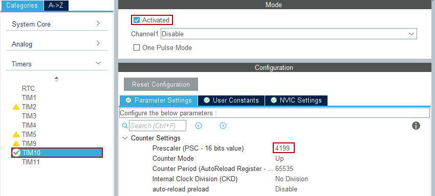
To configure TIM10’s free running counter to run at 20 kHz, we just need to activate it and properly configure its prescaler. In order to do so, we first determine the frequency of the clock that drives the TIM10 peripheral. Switch to the Clock Configuration tab of the CubeMX tool to find out:
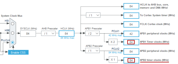
Apparently, two timer clocks exist: APB1 Timer clock and APB2 Timer clock. By diving into the Reset and clock control (RCC) section of the microcontroller’s reference manual, you can find out which one sources the TIM10 peripheral. Turns out it is the APB2 Timer clock. Although in this case it doesn’t matter, because both timer clocks happen to run at the same 84 MHz frequency.
To run the TIM10 free running counter at 20 kHz, we need to set its clock prescaler to 84000 / 20 = 4200. Just keep in mind that the actual 16-bit prescaler value is zero based. So a value of 0, means a prescaler of 1. As such, we should set it to 4199:
This concludes the microcontroller configuration. Click the floppy icon on the toolbar to save the changes. Consequently, the CubeMX tool automatically generates the configuration code into our STM32CubeIDE project.
MicroTBX-Modbus integration
After configuring the microcontroller in our STM32 project, we continue with adding the Modbus communication software stack. As mentioned in the introduction, we’ll use MicroTBX-Modbus for creating our Modbus RTU server. MicroTBX-Modbus is a modern Modbus communication stack, targeting microcontroller based embedded systems. Its aim is to be: easy to use, easy to port, high quality, well maintained, stable and flexible. Since MicroTBX-Modbus builds upon the MicroTBX base component, we’ll start with integrating MicroTBX.
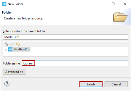
In preparation, we first add a new folder called Library to our STM32CubeIDE project. To do so, right-click the ModbusRtu project in the Project Explorer and select New → Folder from the pop-up menu. On the New Folder dialog, enter Library as the Folder name and click the Finish button:
Next, we flag the newly created Library folder as a Source folder. That way all the source files we’ll add in the next steps get compiled and linked during a build. Right-click the ModbusRtu project in the Project Explorer and select Properties from the pop-up menu. Select the C/C++ General → Paths and Symbols category. On that category’s screen, select the tab Source Location. Click the Add Folder… button to add the newly created Library folder:
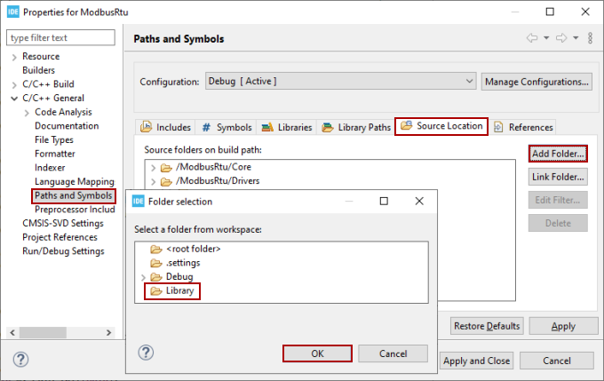
Once done, click the Apply and Close button.
Adding MicroTBX
Download MicroTBX from the releases webpage. At the time of this writing the latest version is 1.3.0, which is the one I downloaded. Extract the downloaded archive to a temporary directory on your PC.
Switch back to the STM32CubeIDE project and create a new microtbx folder as a sub-folder of the previously created Library folder in the project. Next, we’ll add this folder to the Include paths. Open up the project Properties dialog again. This time select the C/C++ Build → Settings category. On the category’s screen, go to section MCU GCC Compiler → Include paths on tab Tool Settings. Click the icon with the little green plus sign and add:
../Library/microtbx
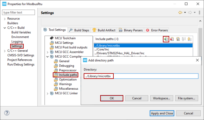
Click the Apply and Close button once done to save the changes and close the Properties dialog.
Next copy over the following list of files, directly into the project’s Library/microtbx folder, so discarding the subfolder structure:
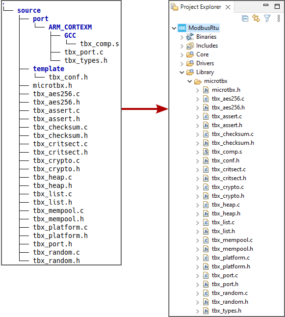
In the next section, we’ll repeat this process for the MicroTBX-Modbus sources.
Adding MicroTBX-Modbus
Download MicroTBX-Modbus from the releases webpage. At the time of this writing the latest version is 0.9.0, which is the one I downloaded. Extract the downloaded archive to a temporary directory on your PC.
Switch back to the STM32CubeIDE project and create a new microtbx-modbus folder as a sub-folder of the previously created Library folder in the project. Next, we’ll add this folder to the Include paths. Open up the project Properties dialog again. This time select the C/C++ Build → Settings category. On the category’s screen, go to section MCU GCC Compiler → Include paths on tab Tool Settings. Click the icon with the little green plus sign and add:
../Library/microtbx-modbus
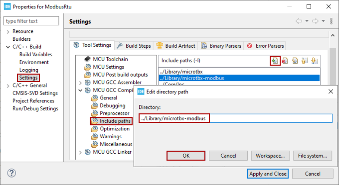
Click the Apply and Close button once done to save the changes and close the Properties dialog.
Next copy over the following list of files, directly into the project’s Library/microtbx folder, so discarding the subfolder structure:
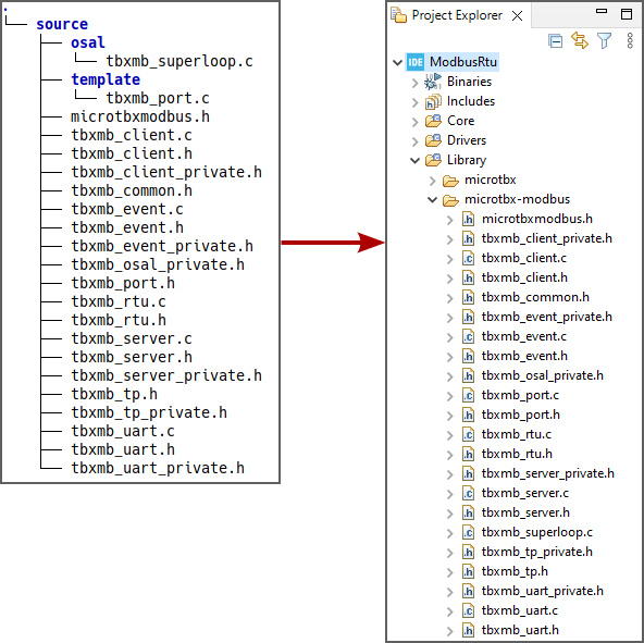
At this point you completed the integration of the MicroTBX-Modbus software stack. You can already rebuild your project to verify that no compile or link errors occur. In the next section we’ll start adding Modbus RTU server functionality to our STM32 application. Afterwards, we’ll implement the hardware specifics in the MicroTBX-Modbus port source-file.
Create the STM32 Modbus RTU server application
With the STM32 project creation and integration of the Modbus communication stack out of the way, it’s time to finally write some code. In this section, we create the Modbus RTU server application for our STM32 firmware project.
Generic Modbus RTU server
Go ahead and open up the main.c source-file in the STM32CubeIDE project. Start by including the MicroTBX and MicroTBX-Modbus related header files:
#include "microtbx.h"
#include "microtbxmodbus.h"
Next, add the declaration of two global variables. Variable modbusTp serves as a handle to the Modbus RTU transport layer object, the modbusServer as a handle to the Modbus server object:
tTbxMbTp modbusTp;
tTbxMbServer modbusServer;
With these variables declared, we can create the Modbus RTU transport layer and Modbus server objects. Add the following lines of code at the start of function main(), before entering the infinite program loop:
modbusTp = TbxMbRtuCreate(10, TBX_MB_UART_PORT1, TBX_MB_UART_19200BPS,
                          TBX_MB_UART_1_STOPBITS, TBX_MB_EVEN_PARITY);
modbusServer = TbxMbServerCreate(modbusTp);
The last step in setting up a basic STM32 Modbus RTU server is the calling of the event task function. Inside the infinite program loop of function main() add this line:
TbxMbEventTask();
Application specific Modbus data tables
In the previous subsection we created a generic Modbus server. However, this one doesn’t actually do much. A typical Modbus server expects requests from a Modbus client for:
- Reading discrete inputs and input registers.
- Writing coils and holding registers.
As stated at the start of this article, our Modbus RTU server should support two 16-bit input registers, starting at zero-based address 30000 in the Modbus data table. Essentially, this means that a Modbus RTU client can request to read two 16-bit values from our server. One at address 30000 and one at address 30001.
The meaning of these 16-bit input register values is up to you. It could be the result of an analog to digital conversion. For example from a temperature sensor. For the sake of this tutorial, we’ll keep it simple and just return constant values:
- When a Modbus client requests the digital input register at address
30000, we’ll return1234. - When a Modbus client requests the digital input register at address
30001, we’ll return5678.
Adding support for the Modbus data tables is a matter of implementing a callback function and registering that callback function with the Modbus server. For reading our two input registers, add the following function above function main():
tTbxMbServerResult ModbusReadInputReg(tTbxMbServer   channel,
                                      uint16_t       addr,
                                      uint16_t     * value)
{
  tTbxMbServerResult result = TBX_MB_SERVER_OK;

  /* Filter on the requested input register address. */
  switch (addr)
  {
  case 30000U:
    *value = 1234U;
    break;

  case 30001U:
    *value = 5678U;
    break;

  default:
    /* Unsupported input register address. */
    result = TBX_MB_SERVER_ERR_ILLEGAL_DATA_ADDR;
    break;
  }

  /* Give the result back to the caller. */
  return result;
}
After implementing the callback function, we just need to register it with the Modbus server. Add the following line after the line that calls function TbxMbServerCreate():
TbxMbServerSetCallbackReadInputReg(modbusServer, ModbusReadInputReg);
Implement the MicroTBX-Modus port
If you made it this far in the tutorial, your STM32 application now contains Modbus RTU server functionality. It supports reading out two input registers starting at address 30000. We just need to complete one more puzzle piece to finish our STM32 Modbus RTU server firmware: The implementation of the port functions.
The port functions connect the microcontroller hardware specific parts to the hardware independent MicroTBX-Modbus communication stack. Adjusting the MicroTBX-Modbus port for your microcontroller essentially means that we just need to implement the following three functions:
TbxMbPortUartInit()TbxMbPortUartTransmit()TbxMbPortTimerCount()
Additionally, we need to call these two functions when their associated events occurred:
TbxMbUartTransmitComplete()TbxMbUartDataReceived()
For more theoretical background information on developing a MicroTBX-Modbus port, refer to the portation section in its user manual. To dive right in, go ahead and open up the tbxmb_port.c source-file in the STM32CubeIDE project. You can find the file in the Library/microtbx-modbus folder.
Preparation
Source-file tbxmb_port.c by default contains the port framework, including a basic reference implementation and code comments describing the missing parts. Luckily, the STM32 HAL drivers, combined with the CubeMX generated initialization code already does most of the heavy-lifting. Therefore, we start by first stripping out the code of the port framework that we won’t need:
- Remove the functions
TbxMbPortUartTxInterrupt()andTbxMbPortUartRxInterrupt(), including their function prototypes. - Remove the
transmitInfo[]array-variable.
Next, we’ll starting adding the basics for our STM32 Modbus port:
- Include the HAL drivers header-file for your STM32 microcontroller. File
stm32f4xx_hal.hin my case, because I selected a STM32F4 based Nucleo board:
#include "stm32g4xx_hal.h"
- Add external declarations for the TIM and UART handle variables. Copy them from
main.cand simply add theexternkeyword in front of it. In the CubeMX tool, I configured the TIM10 timer and the USART2 communication peripherals:
extern TIM_HandleTypeDef htim10;
extern UART_HandleTypeDef huart2;
- Add a local variable declaration, which we will use later on for storing newly received byte values:
static uint8_t rxByte;
Timer counter
With the port preparation work out of the way, we’ll continue with implementing the timer port function TbxMbPortTimerCount(). Remember that we initialized a timer’s free running counter to count at 20 kHz earlier on? This timer port function reads out the current value of the timer’s free running counter.
The CubeMX generated code already handled the configuration of the timer. Just keep it mind that it didn’t actually start the timer counter. We’ll take care of that in this port function as well. Update function TbxMbPortTimerCount() to look like this:
uint16_t TbxMbPortTimerCount(void)
{
  static uint8_t counterStarted = TBX_FALSE;

  /* Start the counter the first time this function is called. */
  if (counterStarted == TBX_FALSE)
  {
    counterStarted = TBX_TRUE;
    __HAL_TIM_ENABLE(&htim10);
  }
  /* Read out the current value of counter. */
  return (uint16_t)__HAL_TIM_GET_COUNTER(&htim10);
}
Make sure to use the correct timer handle. I configured TIM10 and therefore specified htim10.
UART initialization
Next, we continue with the implementation of the TbxMbPortUartInit() port function. We take a shortcut here to keep things simple, yet functional. For this tutorial we know that our STM32 Modbus RTU server only uses one channel (TBX_MB_UART_PORT1). Furthermore, the CubeMX generated code already initialized the associated UART channel for the desired baudrate and communication parameters. Consequently, we can ignore the function parameters and just kick off the reception of the first byte:
void TbxMbPortUartInit(tTbxMbUartPort     port,
                       tTbxMbUartBaudrate baudrate,
                       tTbxMbUartDatabits databits,
                       tTbxMbUartStopbits stopbits,
                       tTbxMbUartParity   parity)
{
  /* Kick off first byte reception. */
  HAL_UART_Receive_IT(&huart2, &rxByte, 1U);
}
Make sure to use the correct UART handle. I configured USART2 and therefore specified huart2. This also applies to the following two sections.
UART reception
Each time the STM32 microcontroller receives a byte value on the UART peripheral, the port should call function TbxMbUartDataReceived() to inform the Modbus stack about the event. Some basic error checking should be done here. The newly received byte value should only be processed if no framing, parity or noise errors were detected during its reception.
The STM32 HAL drivers make this task fairly simple for us. Upon reception of a new byte value, it calls the HAL_UART_RxCpltCallback() function. We merely need to implement this function, do the error checking, call TbxMbUartDataReceived() and start of the reception of the next byte. Add the following function for this:
void HAL_UART_RxCpltCallback(UART_HandleTypeDef * handle)
{
  uint32_t errorCode = HAL_UART_GetError(&huart2);
  /* Only process the byte if no noise, framing or parity error was detected. */
  if ((errorCode & (HAL_UART_ERROR_NE|HAL_UART_ERROR_PE|HAL_UART_ERROR_FE)) == 0U)
  {
    /* Inform the Modbus UART module about the newly received data byte. */
    TbxMbUartDataReceived(TBX_MB_UART_PORT1, &rxByte, 1U);
  }
  /* Restart reception for the next byte. */
  HAL_UART_Receive_IT(&huart2, &rxByte, 1U);
}
UART transmission
When the Modbus stack needs to transmit a number of bytes via UART, it calls function TbxMbPortUartTransmit() in our port source-file. Inside this function, we should start the transmission. With the STM32 HAL drivers, this means we just need to pass on the request by calling function HAL_UART_Transmit_IT():
uint8_t TbxMbPortUartTransmit(tTbxMbUartPort         port,
                              uint8_t        const * data,
                              uint16_t               len)
{
  uint8_t result = TBX_ERROR;

  if (HAL_UART_Transmit_IT(&huart2, (uint8_t *)data, len) == HAL_OK)
  {
    result = TBX_OK;
  }
  /* Give the result back to the caller. */
  return result;
}
Upon data transmission completion, our port should call function TbxMbUartTransmitComplete() to inform the Modbus stack about this event. Again, the STM32 HAL drivers make this task easy for us. It calls the HAL_UART_TxCpltCallback() function when the transmission completes. All that is left for us to do is the implementation of this callback function:
void HAL_UART_TxCpltCallback(UART_HandleTypeDef * handle)
{
  /* Inform the Modbus UART module about the transmission completed event. */
  TbxMbUartTransmitComplete(TBX_MB_UART_PORT1);
}
Testing the Modbus RTU communication
After completing the MicroTBX-Modbus port, our STM32 Modbus RTU server should be all set. Time for the grand finale where we verify that the Modbus RTU communication actually works.
Build and run the firmware
As a first step, build the code by selecting Project → Build Project from the program menu. Alternatively, use the CTRL+b key combination. If you followed the prior steps to a tee, then no compile or link errors should occur. If you do run into a compile or link error, try to find a solution. As a reference, you can download my resulting project: ModbusRtu_NucleoF401RE.zip.
With the Modbus RTU server firmware built, start a debugging session to flash the firmware into the STM32 microcontroller. Select Run → Debug from the program menu or press the F11 key. Once done, start the firmware by selecting Run → Resume from the project menu or press F8. The Modbus RTU server should now be operational on the STM32 board.
Test with QModbus
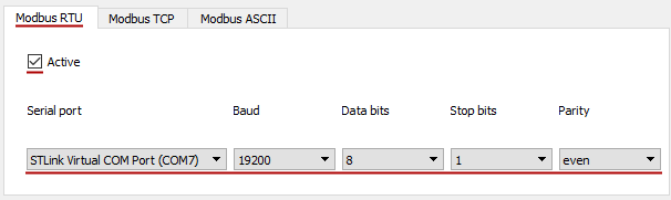
With the Modbus RTU server running, it’s time to test that it actually works. Start the QModbus application on your PC and configure the serial port connection:
- Switch to the Modbus RTU tab.
- Check the Active checkbox.
- Select the serial port that represents the on-board ST-Link’s USB-CDC device.
- Set the baudrate to 19200, data-bits to 8, stop-bits to 1 and the parity to even.
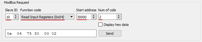
Next, we’ll configure the Modbus request message. We want to read two input registers, starting at address 30000, from a node with identifier 10:
- Set the Slave ID to
10. - Select Function code
Read Input Registers (0x04). - Set the Start address to
30000. - Set the Num of coils to
2.
As a final step, click the Send button to send this request to the Modbus RTU server running on our STM32. If all goes as expected, you should see the values 1234 and 5678 in the response. These are the constant values we assigned to the input registers, when we implemented the ModbusReadInputReg() callback function:
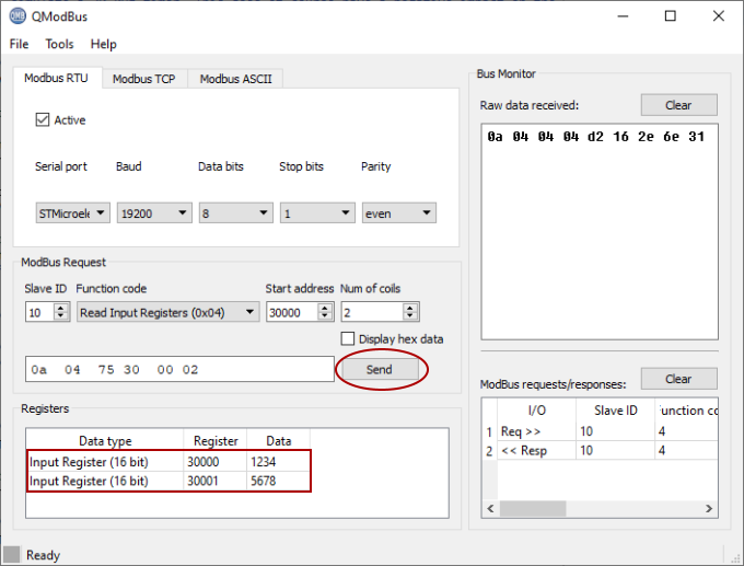
Success! You now have a fully functional Modbus RTU server running on your STM32.
Wrap up
In this tutorial we created a fully operational Modbus RTU server on an STM32 microcontroller system. It focused on a Nucleo-F401RE board. However, you can follow a similar approach for any other STM32 based board, as long you can connect the board somehow to your PC’s serial port. A USB-RS232 adapter, such as the FTDI based ones, can prove useful here.
The demonstration functionality of the built Modbus RTU server is somewhat limited:
- It only supports two input registers and returns a constant value for each.
- The port ignores the communication settings parameters of function
TbxMbPortUartInit()and works on just one channel.
A perfect foundation to add more application specific functionality. Here follow a few ideas of how you can extend it:
- Implement and register a callback function for writing coils. For example, when a Modbus client requests the coil with address
0to be either on of off, change the state of the LED on the board accordingly. Then use QModbus to test it out. - Instead of returning a constant value when reading out the input registers, return an actual sensor value. For example a temperature sensor.
- Improve the implementation of port function
TbxMbPortUartInit()such that it actually properly initializes the UART peripheral for the requests communication settings. Then test it by changing the communication parameters when calling functionTbxMbRtuCreate()in your application. - Rework the implementation of the UART port functions for multichannel support.
The following resources might come in handy, when developing these extensions:
- The MicroTBX-Modbus demo programs. They already contain fully functional ports:.
- The MicroTBX-Modbus user manual and specifically the included API reference.