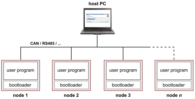
Internally, the OpenBLT bootloader is based on the XCP communication protocol. XCP is a point-to-point protocol for establishing a connection between a host PC and a microcontroller. Now consider a system with multiple nodes, where each node consists of a microcontroller running the OpenBLT bootloader. Can you still perform a firmware update on each individual node? The short answer is: Yes, you can. This article explains how to configure the bootloader for this purpose.
There are several solutions for this scenario. For example, when the nodes are connected to a CAN network, you could assign a different pair of CAN identifiers per node for firmware update purposes. The solution presented in this article strives to be a more generic solution, independent of the communication transport layer.
The foundation of this solution lies in the XCP connect-command. This is a two-byte XCP request packet that the host PC sends to the microcontroller to establish a connection. The first byte is the code of the connect-command, which is always 0xFF. The second byte is a so-called “connection mode”, which can be interpreted any way you like. In this article, the “connection mode”-byte will be interpreted as a node address. This enables up to 256 nodes to be individually addressed.

Bootloader preparation
The node addressing solution is explained with the help of the OpenBLT 1.5.0 demo programs for the Olimex STM32-P103 board, configured for building with the GNU ARM Embedded toolchain. In the example described in this article, it is assumed that multiple nodes are connected on a CAN network. The first step is therefore to prepare the bootloader for supporting firmware updates via CAN only. Open up the “blt_conf.h” configuration header-file in the source-code editor of your choice. It is located in directory: ./Target/Demo/ARMCM3_STM32F1_Olimex_STM32P103_GCC/Boot/.
Locate the following lines:
#define BOOT_COM_CAN_ENABLE             (1)
#define BOOT_COM_UART_ENABLE            (1)
#define BOOT_FILE_SYS_ENABLE            (1)
Change these lines to:
#define BOOT_COM_CAN_ENABLE             (1)
#define BOOT_COM_UART_ENABLE            (0)
#define BOOT_FILE_SYS_ENABLE            (0)
Next, rebuild the bootloader. This is achieved by running the command make clean allfrom the directory where the “blt_conf.h” configuration header-file is located. You now have a bootloader that supports firmware updates via CAN only.
Note that the bootloader shrunk is size quite a bit too, as a side effect of disabling some functionality. Initially, it was about 20 kB and now it is less that 6 kB. The Olimex STM32-P103 demo programs are configured such that the first 24 kB of flash is reserved for the bootloader. This works fine for the example in this article, but theoretically this reserved amount of flash memory could be lowered. Refer to this blog article for details on how to reconfigure and optimize the bootloader for a low ROM footprint.
Bootloader reconfiguration
The first steps in making a node individually addressable for a firmware update is by enabling the hook-function XcpPacketReceivedHook()and by setting the address of the node. It can be any value in the range of 0 to 255. In this example, a node address of 3 is assigned. Open up the “blt_conf.h” configuration header-file in your source-code editor and add the following lines:
/**********************************************************************
*   X C P   C O M M U N I C A T I O N   C O N F I G U R A T I O N
**********************************************************************/
/** \brief Enable or disable the hook function that gets called each
 *         time an XCP packet was received from the host.
 */
#define BOOT_XCP_PACKET_RECEIVED_HOOK   (1)

/** \brief The second byte in the XCP connect command (connection mode)
 *         is used as a node address in the range 0..255. Configure the
 *         address of this specific node with this macro.
 */
#define BOOT_XCP_CONNECT_MODE_NODE_ADDR (3)
Next, implement the XcpPacketReceivedHook()function. This function gets called each time an XCP packet is received from the host PC. The implementation should be such that the XCP communication module ignores connect requests unless they are specifically address to this node (BOOT_XCP_CONNECT_MODE_NODE_ADDR). Open up the “hooks.c” source-file in your source-code editor and add the hook-function:
/**********************************************************************
*   X C P   C O M M U N I C A T I O N   H O O K   F U N C T I O N S
**********************************************************************/
#if (BOOT_XCP_PACKET_RECEIVED_HOOK > 0)
/******************************************************************//**
** \brief     Callback that gets called when a new XCP packet was
**            received from the host, before it got processed by the
**            XCP communication module.
** \param     data Pointer to byte buffer with packet data.
** \param     len Number of bytes in the packet.
** \return    BLT_TRUE is the packet was processed by this function,
**            BLT_FALSE if the packet should be processed by the XCP
**            protocol as usual.
**
**********************************************************************/
blt_bool XcpPacketReceivedHook(blt_int8u *data, blt_int8u len)
{
  blt_bool result = BLT_FALSE;

  /* Intercept the connect command which consists of two bytes with the
   * first byte always being 0xFF and the second byte being the
   * 'connection mode', which is used to pass on a node address in this
   * example. Only allow the connection to be established, if it is
   * addressed to us.
   *
   * -----------------------
   * | 0xFF | node address |
   * -----------------------
   *
   */
  /* Is this the connect command, but not addressed to us? */
  if ( (data[0] == 0xFF) &&
       (len == 2) &&
       (data[1] != BOOT_XCP_CONNECT_MODE_NODE_ADDR) )
  {
    /* Do not establish a connection simply by ignoring this connect
     * command. This is achieved by informing the XCP communication
     * module that this packet was fully processed by this function
     * and no further processing is needed by the XCP communication
     * module.
     */
    result = BLT_TRUE;
  }
  /* Give the result back to the caller. */
  return result;
} /*** end of XcpPacketReceivedHook **/
#endif /* BOOT_XCP_PACKET_RECEIVED_HOOK > 0 */
The reconfiguration of the bootloader is now complete. All that needs to be done is building the bootloader by running the command make alland flashing the updated bootloader into the internal flash memory of the STM32F103 microcontroller, using a debugger interface such as a Segger J-Link or an ST-LINK.
User program reconfiguration
The demo user program contains functionality to detect new firmware update requests from the host PC. It does this by intercepting the previously described XCP connect-command. Upon detection of the XCP connect-command, it activates the bootloader by issuing a software reset.
If the firmware update is not addressed to this node, the bootloader will ignore it and simply start the user program again. This logic works, but it does activate the bootloader unnecessarily. To prevent the bootloader from being activated for a firmware update that is not addressed to the node, open the “boot.c” source-file in your source-code editor. It is present in directory: ./Target/Demo/ARMCM3_STM32F1_Olimex_STM32P103_GCC/Prog/.
Locate the following lines in function BootComCanCheckActivationRequest():
/* check if this was an XCP CONNECT command */
if ((RxMessage.Data[0] == 0xff) && (RxMessage.Data[1] == 0x00))
{
  /* connection request received so start the bootloader */
  BootActivate();
}
And change them to:
/* check if this was an XCP CONNECT command addressed to this node */
if ((RxMessage.Data[0] == 0xff) &&
    (RxMessage.Data[1] == BOOT_XCP_CONNECT_MODE_NODE_ADDR))
{
  /* connection request received so start the bootloader */
  BootActivate();
}
This small change makes sure that the bootloader only gets activated when the firmware update is addressed to this node. Complete the changes by building the user program with the command make all.
Configure the host PC tools
Now that the changes are made on the microcontroller side in both the bootloader and the user program, the last step is configuring the host PC tools to address the correct node. Remember that the solution presented in this article enters the node address value as the “connection mode”-byte in the XCP connect command. Both MicroBoot and BootCommander support the configuration of the “connection mode”-byte.
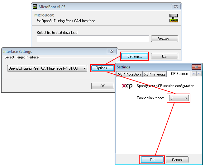
To correctly address the node from the example in this article, the “connection mode”-byte should be set to 3, as this is the value we assigned to macro BOOT_XCP_CONNECT_MODE_NODE_ADDR.
MicroBoot
In MicroBoot, the “connection mode”-value is configured on the “XCP Session”-tab as can be seen in the following screenshot:
BootCommander
In BootCommander, the “connection mode”-value is configured via the “-cm=[value]” command-line option. Assuming that the user program S-record is located in the ./Host/ directory, the following BootCommander command-line would sarts the firmware update for node 3:
BootCommander -cm=3 -t=xcp_can -d=peak_pcanusb demoprog_olimex_stm32p103.srec
Conclusion
This article presented a solution for performing a firmware update on an individually addressed node in a network with multiple nodes. It is a generic solution independent of the communication transport layer.
The code examples described the configuration of just one node for this purpose, however the same principle can be applied to all other network nodes, by just changing the node address value that was defined with macro BOOT_XCP_CONNECT_MODE_NODE_ADDR.
Instead of a static node address value, macro BOOT_XCP_CONNECT_MODE_NODE_ADDRcould be used to read out the node address value from for example a fixed address location in EEPROM. This way the node address can be dynamically set.