The OpenBLT bootloader offers a versatile and flexible solution for in-field firmware updates on your embedded system. It’s a mature and stable bootloader solution. Pretty much Flash-and-forget. Over the last decade no one reported that firmware updates stopped working for some reason. Nonetheless, a situation might arise where you want to update the bootloader itself. Perhaps you added a new feature or simply just want to upgrade to the latest stable release of OpenBLT. Not a problem if you can still connect a JTAG or SWD type programming interface.
However, that is not always possible. You might not offer a connector for this on your final PCB or it’s no longer physically accessible. Some users even secure their microcontroller such that access with a debugger or programming interface is completely locked out. In this scenario the following question pops up in my inbox: Can I update the OpenBLT bootloader itself? Well, no..but also yes. Read on for more details.
Updating the OpenBLT bootloader itself is risky. It involves erasing the old bootloader and programming a new one. If something goes wrong during this procedure, such as a power loss or communication glitch, your system no longer works…at all! For this reason, the OpenBLT bootloader does not feature functionality for updating itself.
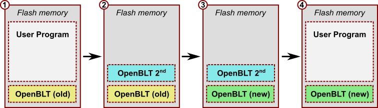
That said, it is possible to update the bootloader, as you can see in the illustration above. The trick is to use a secondary OpenBLT bootloader. This article explains how this procedure works. Be warned though that it always comes with a small risk as described before. If you take the right safety precautions, it’s fairly safe though.
What do you need
To complete the outlined steps for updating the OpenBLT bootloader itself, you need the following:
- A microcontroller system running the OpenBLT bootloader, such that you can make firmware updates of your user program, using the bootloader.
- A software development environment for building the bootloader from source code.
For demonstration purposes, I decided on using the Nucleo-L476RG board. I already built and programmed the demo bootloader and user program for this board, as described on the Wiki with the help of the IAR Embedded Workbench for ARM. I’ll use RS232 communication for the actual update. The Nucleo-L476RG board conveniently features an virtual COM port, through the USB connector of its on-board ST-Link interface. Just connect the board to your PC with the USB cable. It both powers the board and registers a COM port on your PC.
Note that you don’t actually need a debugger or programmer interface anymore, once you flashed the initial version of the OpenBLT bootloader.
Step 1 – Prepare your new version of the OpenBLT bootloader
Updating the OpenBLT bootloader is the entire purpose of this article. This assumes that you already prepared a new version of the OpenBLT bootloader. For demonstration purposes, I’ll create one here myself. The OpenBLT demo bootloader, which I programmed onto my Nucleo-L476RG board, toggles an LED every 100 milliseconds. It serves as a visual indicator to recognize that the bootloader runs. In contrast, the demo user program for the board, toggles the LED at a slower 500 milliseconds rate.
My new version of the OpenBLT bootloader for this article, will toggle the LED even faster: every 50 milliseconds. To achieve this, I updated the implementation of function CopInitHook() to look like this:
void CopInitHook(void)
{
  /* this function is called upon initialization. might as well use it to
   * initialize the LED driver. It is kind of a visual watchdog anyways.
   */
  LedBlinkInit(50);
}
After building the modified bootloader with the IAR Embedded Workbench, it outputs the S-record of the new bootloader. By default, it is called openblt_stm32l476.srec and I renamed it to openblt_stm32l476_new.srec.
To recap: We now have our new OpenBLT bootloader in file openblt_stm32l476_new.srec. It represents the green colored “OpenBLT (new)” block in the illustration. On the Nucleo-L476RG board, I have the regular demo bootloader running, which I used to program the demo user program:
Step 2- Create and program the secondary OpenBLT bootloader
In this section, we’ll create the secondary bootloader. It’s the aqua colored “OpenBLT 2nd” block in the illustration. This is where we need to do most of the work. It’s worth the effort though, because you can reuse the developed secondary bootloader, whenever you want to update the OpenBLT bootloader itself. We’ll use the IAR project of the Nucleo-L476RG demo bootloader as a starting point. So the same bootloader that is currently running on the board: the yellow colored “OpenBLT (old)”. Later on in this section, we’ll use the regular bootloader to program and start the secondary bootloader.
Configure the bootloader as if it’s a user program
From the perspective of the regular bootloader, our secondary bootloader behaves just like a user program. As such, we also need to configure it as a user program. The port specifics Wiki page details all the changes we need to make to our secondary bootloader, such that we can program it with the regular bootloader. I’ll go through this step-by-step here. Just keep in mind that the presented steps are specific for the STM32L4 microcontroller family. Refer to the WIki in case you use a different microcontroller family.
Move the base address forward
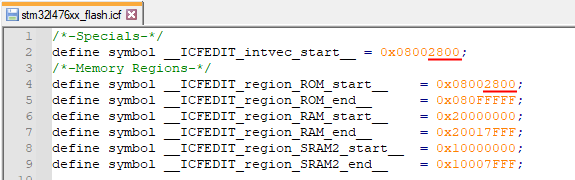
The regular bootloader occupies the first part of flash memory. In the case of the Nucleo-L476RG demo bootloader, this is the first 10 Kbyte (0x2800). You can find out by looking at the commented out entries in the flash driver’s flashLayout[] array. Consequently, we need to move the base address of our secondary bootloader 10 Kbyte forward.
By default, the linker script locates the bootloader at the start of flash memory: 0x08000000. For our secondary bootloader, we need to change this to 0x08002800. You can do this by editing the stm32l476xx_flash.icf file of the IAR demo bootloader. It should look like this:
Add a placeholder for the signature checksum
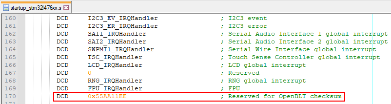
At the end of the firmware update, the regular (let’s call it primary) bootloader calculates and writes a signature checksum value at a fixed address inside the flash area of the secondary bootloader. The primary bootloader’s configuration macro BOOT_FLASH_VECTOR_TABLE_CS_OFFSET determines the signature checksum location. Its defaults value for the STM32L4 port is address 0x188. This happens to be right after the vector table of the secondary bootloader.
To make sure the primary bootloader does not overwrite other important program data of our secondary bootloader, we need to reserve space for the 32-bit signature checksum value. You can do so by adding one extra dummy entry at the end of the vector table:
To verify that this dummy value is actually located at the correct location of 0x188 (BOOT_FLASH_VECTOR_TABLE_CS_OFFSET) after the start of the secondary bootloader in flash, you can build the secondary bootloader and inspect its S-record:
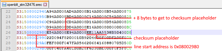
With a basic understanding of the S-record format, you can extract that the signature checksum is located at memory address 0x08002980 + 8 = 0x08002988. In the previous section, we set the start address of the secondary bootloader in flash to 0x8002800. This means that the offset from the start of the secondary bootloader to the checksum placeholder is: 0x08002988 – 0x08002800 = 0x188. This matches the value of macro BOOT_FLASH_VECTOR_TABLE_CS_OFFSET so all is good. Note that you can reconfigure the value of macro BOOT_FLASH_VECTOR_TABLE_CS_OFFSET by redefining it in the bootloader’s configuration header file blt_conf.h.
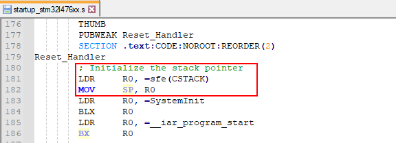
Explicitly initialize the stackpointer
On the ARM Cortex-M4 the first entry into the vector table holds the initialization value for the stackpointer, which is automatically loaded into the CPU’s stackpointer register upon reset. After a reset, the primary bootloader first starts and, if a valid user program is present, it is the bootloader’s responsibility to start the user program. This unfortunately means that the automatic initialization of the CPU’s stackpointer register does not work for the user program. For this reason the user program, and therefore also the secondary bootloader, needs to explicitly set the initial value of the CPU’s stackpointer register in the reset interrupt service routine:
Configure the vector table base address
Before the primary bootloader starts the user program (or secondary bootloader), it automatically reconfigures the base address of the interrupt vector table. In our case, it will be set to 0x08002800, which is the start of our secondary bootloader in flash. Unfortunately, the default system initialization function SystemInit() from ST’s driver library, overwrites this change. This function is implemented in source file system_stm32l4xx.c.
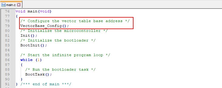
To correct this, you need to explicitly set the base address of the interrupt vector table as the first thing in function main(). Here is an example of how this can be done when using the IAR Embedded Workbench as your development environment.
Add the following function to main.c:
void VectorBase_Config(void)
{
  /* The constant array with vectors of the vector table is declared
   * externally in the c-startup code.
   */
  extern const unsigned long __vector_table[];

  /* Remap the vector table to where the vector table is located for
   * this program.
   */
  SCB->VTOR = (unsigned long)&__vector_table[0];
}
Once added, call this function at the start of main():
Allow reprogramming of the bootloader’s flash sectors
At this point, we configured the secondary bootloader as if it’s a user program. Meaning that we can program it already using the primary bootloader. However, a few more tweaks are needed for the secondary bootloader to work. These are presented in this, and the next section.
The bootloader’s flash driver defines the sectors of flash memory in array flashLayout[]. This is an important array, because it also controls which sectors the bootloader is not allowed to erase and reprogram. Namely the flash area reserved for the bootloader itself. Otherwise it would be possible to accidentally erase the bootloader. Here’s what the current flashLayout[] looks like. It’s located in the STM32L4 port’s flash.c file:
![Screenshot of what the original flashLayout[] array looks like.](https://www.feaser.com/en/blog/wp-content/uploads/2022/05/flash_layout_org.png)
As you can see, the first 5 sectors of 2 Kbyte are commented out. So the bootloader is protected from erasing the first 0x2800 bytes of flash memory. Absolutely necessary for the primary bootloader. However, the secondary bootloader needs exactly the opposite. The role of the secondary bootloader is to reprogram the primary bootloader. For the secondary bootloader to work, we therefore need to update its flashLayout[] array such that it contains just the sectors where the primary bootloader resides. In our case:
static const tFlashSector flashLayout[] =
{
  { 0x08000000, 0x00800 },           /* flash sector  0 - 2kb */
  { 0x08000800, 0x00800 },           /* flash sector  1 - 2kb */
  { 0x08001000, 0x00800 },           /* flash sector  2 - 2kb */
  { 0x08001800, 0x00800 },           /* flash sector  3 - 2kb */
  { 0x08002000, 0x00800 }            /* flash sector  4 - 2kb */
};
Override the checksum write and verification functionality
This section presents the final puzzle piece to getting a functional secondary bootloader ready. At the end of the firmware update, the bootloader calculates and writes the signature checksum value. Afterwards, it verifies the checksum value and, if correct, it starts the newly programmed firmware. Exactly what you want for the primary bootloader, but not for the secondary bootloader. The secondary bootloader doesn’t program a user program, but a new version of the primary bootloader.
Therefore we need to disable the signature checksum writing part. Furthermore, we should make sure the checksum verification always fails, because then the secondary bootloader will simply keep itself active and not attempt to start a user program. Which of course is not present, because we used the secondary bootloader to update the primary bootloader and not a regular user program.
It’s pretty simple to achieve this. In the bootloader’s configuration blt_conf.h header file, set the configuration macro BOOT_NVM_CHECKSUM_HOOKS_ENABLE to 1:
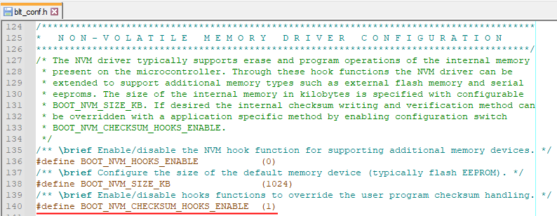
The bootloader’s internal signature checksum writing and verification is now disabled. We can implement our own version in the enabled hook-functions NvmWriteChecksumHook() and NvmVerifyChecksumHook(). You can find these functions in source file hooks.c. Update their implementation like this:
blt_bool NvmVerifyChecksumHook(void)
{
  /* Always fail to so that the secondary bootloader keeps running
   * and never attempts to start a non-present user program.
   */
  return BLT_FALSE;
}

blt_bool NvmWriteChecksumHook(void)
{
  /* Don't actually write the checksum, because the secondary bootloader
   * doesn't use it and no space is reserved for it.
   */
  return BLT_TRUE;
}
Program the secondary bootloader using the primary bootloader
In the previous sections we made all the changes to the standard OpenBLT bootloader to configure it as a secondary bootloader. Save all your changes and build this new secondary bootloader with your development environment. IAR Embedded Workbench for this demonstration.
Note that you can reuse this secondary bootloader, so you’ll only have to go through this effort once. I renamed the resulting S-record of the newly built secondary bootloader to openblt_stm32l476_2nd.srec.
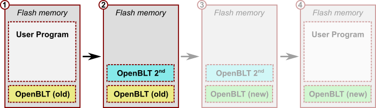
Now it’s time to use the primary bootloader, to program our newly created secondary bootloader. Start MicroBoot as if you were to perform a firmware update as usual. The only difference is that you now select the S-record of the secondary bootloader, openblt_stm32l476_2nd.srec in my situation:
At this point the Nucleo-L476RG board has both the primary and the secondary bootloaders in flash memory. After a reset, the primary bootloader automatically starts the secondary bootloader:
Step 3 – Program your new OpenBLT bootloader
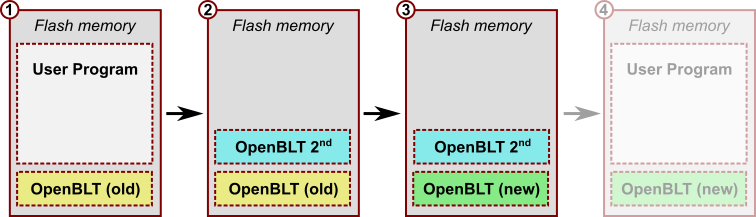
With the secondary bootloader running on the microcontroller, we can perform yet another firmware update. This time for updating the primary bootloader. Erasing the yellow colored “OpenBLT (old)” and programming the green colored “OpenBLT (new)”.
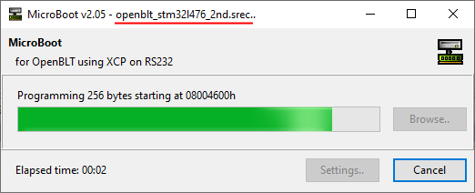
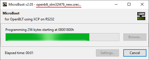
During Step 1, I already created the S-record of the new primary bootloader. I named it openblt_stm32l476_new.srec. Start MicroBoot and perform a firmware update as usual. Just select the S-record of the new primary bootloader. The firmware update request will be detected and processed by the currently running secondary bootloader:
Upon completion, the situation in flash memory resembles this:
Step 4 – Restore your user program
At this point, we completed the update of the primary OpenBLT bootloader. We just need to do a bit of clean up work, because the secondary bootloader is still present. We need to get rid of it and restore our original user program.
There is just one challenge: After a reset, the primary bootloader automatically starts the secondary bootloader. The secondary bootloader cannot be used to restore the user program. Simply because it is located in the same flash region that the user program would go to. Furthermore, the secondary bootloader can only operate on the flash region of the primary bootloader.
To workaround this problem, we need to inform the primary bootloader to bypass the starting of the secondary bootloader. This is where OpenBLT’s timed backdoor mechanism comes into play. After every reset, the bootloader remains running for a certain amount of time. Macro BOOT_BACKDOOR_ENTRY_TIMEOUT_MS determines how long. The default is typically 500 milliseconds.
The trick to restoring the user program with the new primary bootloader is to keep the microcontroller powered down or in a reset state. Next, start the firmware update procedure of the user program with MicroBoot. Once started, power up the microcontroller or release it from the reset state. The primary bootloader will detect the firmware update request, coming from MicroBoot during the timed backdoor time. Instead of starting the secondary bootloader, it will process the firmware update. Upon completion, it will starts the newly programmed firmware, which is the original user program:
Wrap up
This article explained in detail how you can update the OpenBLT bootloader itself, with the help of a secondary bootloader. The secondary bootloader is a slightly modified version of the OpenBLT bootloader. Creating the secondary bootloader involves some work. Fortunately, you only need to do the work once, because you can reuse the created secondary bootloader, each time you want to update the OpenBLT bootloader.
The procedure for updating the OpenBLT bootloader involves these steps:
- Create your new OpenBLT bootloader in S-record format.
- Use the existing OpenBLT bootloader to perform a firmware update for programming the secondary OpenBLT bootloader.
- With the secondary OpenBLT bootloader running, perform a firmware update for programming your new OpenBLT bootloader.
- Restore your original user program with yet another firmware update. This time enter the (primary) OpenBLT bootloader using timed backdoor mechanism.
As mentioned in the introduction, updating the OpenBLT bootloader itself, involves risk. A problem during step 3 likely results in an unusable system. The only way to make the system usable again, is to restore the primary OpenBLT bootloader with the help of a JTAG or SWD type programming interface. With that in mind, take proper precautions to mitigate the risk. In any case, use the described procedure to update the OpenBLT bootloader at your own risk.